Installing an inverter and battery system requires careful planning and a working knowledge of several technical areas, including system sizing, wiring standards, and safety protocols.
Errors in any of these areas can result in equipment damage, electrical faults, or personal injury.
Understanding each step before beginning the installation reduces these risks and supports a functional, code-compliant outcome.
What Size Inverter Does Your Home Actually Need?
Selecting an appropriately sized inverter requires calculating the combined wattage of all appliances intended to operate simultaneously. This calculation must account for both continuous power draw and surge loads, which are the temporary spikes in power consumption that occur when certain appliances, particularly those with motors, start up.
As a general guideline, the inverter’s continuous power output rating should exceed the total calculated load by at least 20%. This buffer accommodates unexpected demand increases and reduces the risk of overloading the unit.
For setups involving sensitive electronics such as medical equipment, computers, or audio systems, a pure sine wave inverter is the appropriate choice. These units produce a cleaner electrical output that more closely replicates grid power, reducing the likelihood of interference or damage to precision equipment. Modified sine wave inverters are a lower-cost alternative but may cause performance issues with certain devices.
Battery capacity must also correspond to the anticipated power demand. An undersized battery bank will deplete rapidly under load, regardless of the inverter’s rated capacity. Matching these two components ensures consistent and reliable power delivery.
Using manufacturer-provided or industry-standard sizing calculators can help verify that a chosen configuration meets both present requirements and potential future increases in power consumption. Consulting a qualified electrician or energy systems professional is advisable when sizing larger or more complex installations. Installers who hold NABCEP certification bring a verified level of technical expertise to battery and inverter system designs, which can be particularly valuable when tailoring a setup to a specific home’s energy profile.
Pure Sine Wave vs. Modified Sine Wave: Which Do You Need?
When selecting between a pure sine wave and a modified sine wave inverter, the primary factor to consider is the type of equipment being powered. Pure sine wave inverters are necessary for sensitive electronics such as laptops, medical devices, and audio equipment, as these devices require a stable, consistent power output. Pure sine wave inverters typically operate at efficiency rates above 90% and provide adequate surge capacity to handle the initial power draw during device startup.
Modified sine wave inverters are a functional option for basic appliances such as fans and incandescent lights, which do not require precise power quality. However, modified sine wave inverters operate at lower efficiency levels and can introduce electrical interference, which may affect the performance or longevity of certain devices. Some motors and transformers may also run warmer when powered by modified sine wave inverters, potentially shortening their operational lifespan.
From a cost perspective, pure sine wave inverters carry a higher price point than modified sine wave models. This cost difference reflects the more complex circuitry required to produce a stable output. For applications where device compatibility and power quality are critical, the additional cost of a pure sine wave inverter is justified. For basic, non-sensitive applications, a modified sine wave inverter represents a more economical option. The decision should be based on a straightforward assessment of the devices being powered and their specific power requirements.
Tools and Materials to Gather Before Installation Day
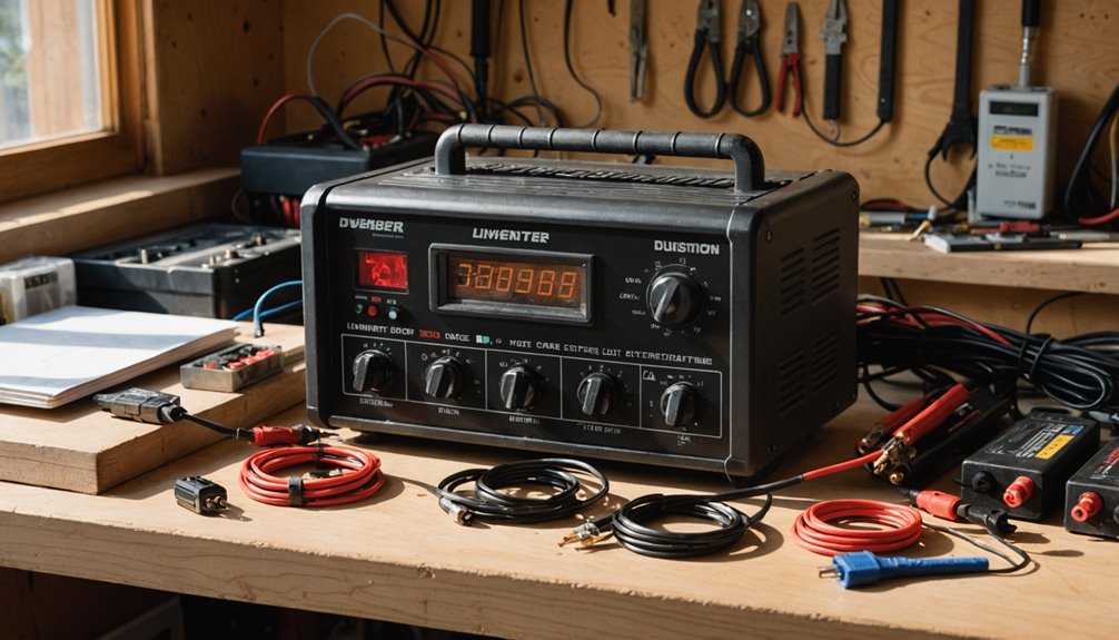
Before beginning an inverter installation, assembling the necessary tools and materials in advance reduces the likelihood of delays and errors during the process. The core tools required include insulated wire strippers, crimping tools, and a multimeter for verifying electrical connections and measurements. DC cables and connectors must be selected according to the inverter’s current specifications to ensure compatibility and safe operation.
Battery configuration requires appropriate circuit breakers and fuses, which serve as overload protection for the system. The inverter should be mounted in a location that is dry, well-ventilated, and accessible, as these conditions support both safe operation and long-term performance. The mounting system itself should be structurally adequate for the weight and dimensions of the unit.
Personal protective equipment is a standard requirement for this type of work. Insulated gloves and safety goggles protect against electrical hazards, and a fire extinguisher should be kept within reach throughout the installation process. These precautions align with general electrical safety standards and reduce the risk of injury or equipment damage.
Essential Safety Precautions Before You Touch Any Wiring
Before touching any wiring, five foundational safety steps should be followed to protect both personnel and equipment. First, disconnect all electrical power sources, including AC and DC breakers, before approaching an inverter or battery system. Second, wear appropriate personal protective equipment, specifically insulated gloves and safety goggles. Third, ensure adequate ventilation in the workspace to reduce the concentration of battery fumes. Fourth, keep a fire extinguisher within reach and confirm familiarity with the nearest emergency exit. Fifth, consult local electrical codes and manufacturer instructions prior to beginning work. Adherence to these steps reduces the risk of electrical injury, equipment damage, and other hazards associated with improper wiring procedures.
How to Pick the Right Spot to Mount Your Inverter
Selecting an appropriate mounting location for an inverter directly affects system performance and operational lifespan. The installation site should be cool, dry, and well-ventilated to support adequate airflow and prevent thermal buildup. Exposure to direct sunlight or proximity to heat-generating appliances should be avoided, as elevated ambient temperatures reduce inverter efficiency and accelerate component wear.
Positioning the inverter close to both the battery bank and the electrical panel minimizes cable length, which reduces resistance and limits voltage drop across the system. The mounting surface should be structurally solid and free from significant vibration. Most manufacturers specify a vertical mounting orientation to facilitate proper internal airflow, and these specifications should be followed as outlined in the product documentation.
Sufficient clearance around the unit is necessary for heat dissipation and to allow routine maintenance access. Inadequate clearance restricts airflow and can cause the unit to operate at elevated temperatures, increasing the likelihood of premature failure. Adhering to manufacturer guidelines and established electrical standards during installation supports consistent, long-term system reliability.
How to Connect Your Battery Bank to the Inverter
Connecting a battery bank to an inverter involves several technical considerations that directly affect system performance and safety.
Cable sizing is determined by the maximum current draw of the inverter. Undersized cables introduce resistance, generate heat, and reduce system efficiency. The cable gauge should be selected based on both current capacity and cable length, referencing standard ampacity tables for the appropriate wire type.
Battery configuration affects both voltage and capacity. Parallel connections increase amp-hour capacity while keeping voltage constant. Series connections increase voltage. Most battery bank configurations use a combination of both to achieve the required voltage and capacity for the intended load.
Physical placement of the inverter relative to the battery bank matters for practical reasons. Shorter cable runs reduce resistive losses and voltage drop, which becomes more significant at higher current draws. Where possible, the inverter should be mounted within close proximity to the battery bank.
Terminal connections must match the manufacturer’s specifications for torque and connector type. Loose connections create resistance points that generate heat and can cause premature component failure. Polarity must be verified before completing any connection, as reversed polarity can permanently damage the inverter.
Prior to commissioning, an insulation resistance test confirms the integrity of the wiring and identifies any faults in the system. This test measures the resistance between conductors and ground, with acceptable values depending on system voltage and applicable electrical standards.
How to Wire the Inverter Into Your Main Electrical Panel
Wiring an inverter into a main electrical panel requires careful attention to safety protocols and local electrical codes. Before beginning, disconnect all power sources to eliminate the risk of electrical shock or equipment damage. Select the appropriate wire gauge based on the inverter’s output current rating to prevent overheating and potential fire hazards.
Connect the inverter’s output to a dedicated circuit breaker within the main panel, sized according to the inverter’s rated output capacity. A transfer switch is a necessary component in this configuration, as it isolates the inverter from the utility grid. Without this isolation, power backfeeding can occur during outages, creating hazardous conditions for utility workers and potentially damaging equipment.
Verify that the inverter’s input voltage specifications align with the battery bank’s output voltage before completing any connections. Voltage mismatches can damage both the inverter and connected equipment. Once all connections are secured, use a multimeter to measure voltage levels at critical points in the circuit, confirming that readings fall within acceptable ranges before restoring power to the panel.
Given the complexity and inherent risks of working with main electrical panels, consulting a licensed electrician is advisable, particularly where local codes require permitted work or professional installation. Documentation of the installation, including wiring diagrams and component specifications, should be maintained for future reference and inspection purposes.
How to Add Solar Panels and a Charge Controller to Your System
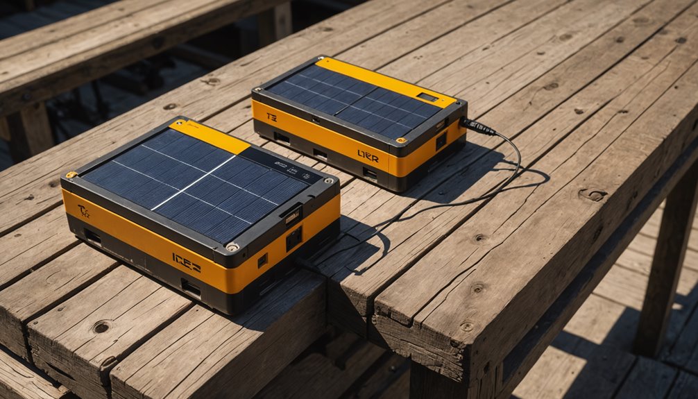
Adding solar panels to an inverter system requires selecting panels whose voltage and power output specifications align with the inverter’s requirements. This compatibility ensures stable energy conversion and consistent battery backup operation. Panels can be wired in series to increase voltage or in parallel to increase current, based on the specific demands of the system.
A charge controller, either PWM or MPPT type, is necessary to regulate the voltage and current delivered to the battery bank. The charge controller’s maximum DC input voltage rating must exceed the combined output voltage of the connected panels to avoid equipment damage. Monitoring the charge controller’s performance indicators and adjusting its settings as needed helps sustain appropriate charging rates and prolong battery service life.
How to Configure and Test Your Inverter After Installation
After installing solar panels and a charge controller, configuring and testing the inverter is a necessary step to ensure safe and efficient operation. Access the manufacturer’s interface to define key parameters, including grid code compliance and output mode settings, which vary depending on regional electrical standards and system requirements.
Prior to powering on the inverter, perform an insulation resistance test. This procedure identifies potential faults in the wiring insulation that could otherwise create electrical hazards during operation. Once the insulation test confirms acceptable resistance levels, use a multimeter or clamp meter to measure voltage, current, and system efficiency under operating conditions. These readings verify that the inverter is performing within its specified range.
If the system is grid-tied, configure the automatic transfer switch feature to manage transitions between grid power and backup power during outages. This function reduces interruption time and maintains load continuity without manual intervention.
Ongoing monitoring of the inverter’s control panel is important for identifying error codes that may indicate performance issues or faults. When error codes appear, cross-reference them with the manufacturer’s troubleshooting guide to determine the appropriate corrective action. Consistent monitoring during both the testing phase and normal operation supports early detection of problems and helps maintain system reliability over time.
How to Maintain Your System and Diagnose Common Faults
Regular maintenance is essential for the safe and efficient operation of inverter and battery systems. Solar panels and air intake filters should be cleaned every six months to sustain solar charging performance. Battery terminals require monthly inspection for corrosion, with loose connections addressed promptly to prevent resistance buildup and potential damage.
To preserve battery health, a full discharge and recharge cycle should be performed monthly. Flooded lead-acid batteries additionally require equalization charges every 90 days to balance cell voltages and prevent sulfation. The inverter’s control panel should be monitored consistently for error codes, as these indicate specific system faults that require attention.
Fault diagnosis involves using a multimeter to measure voltage and current readings against manufacturer specifications. Stable electrical parameters on the inverter charger confirm correct system operation, while deviations from expected values indicate areas requiring further investigation or component replacement.